Integrated Building Technology (IBT) is a series of architecture courses that inform students on different building materials, environmental factors of design, and exposure to new program and rendering skills.

Sun shading rendering exercise that was self-designed and built in Rhino3D. The renderings for each time stamp were developed via V-Ray.

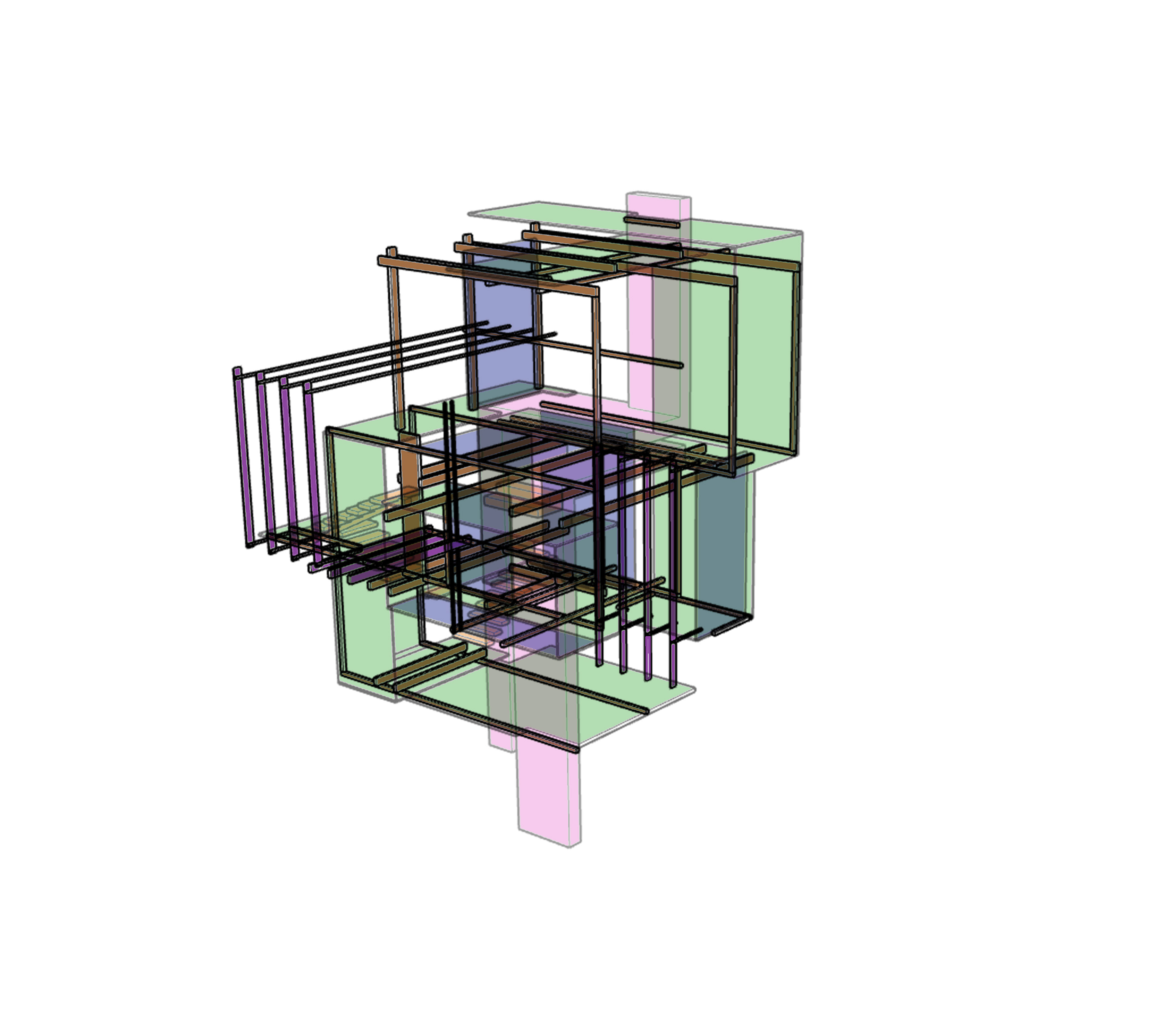
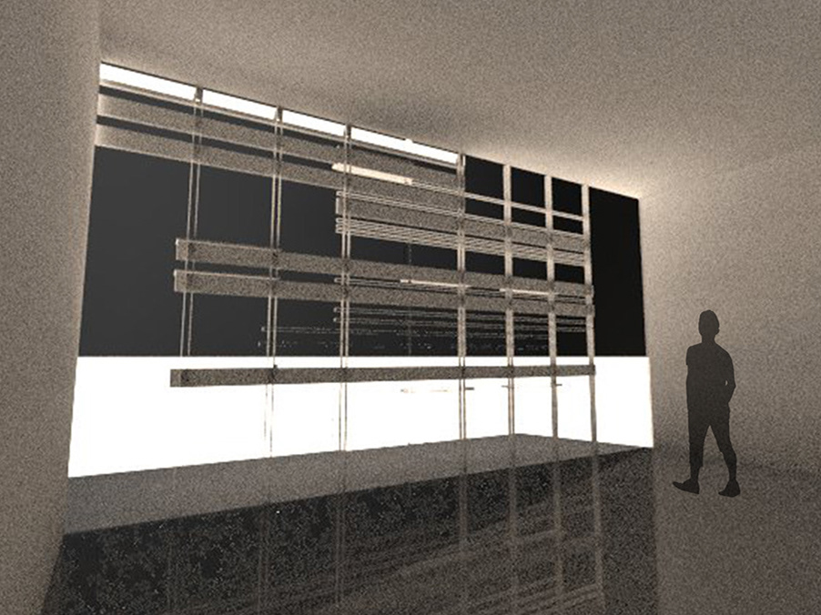
Shading systems exercise done in Photoshop on a Rhino model file.

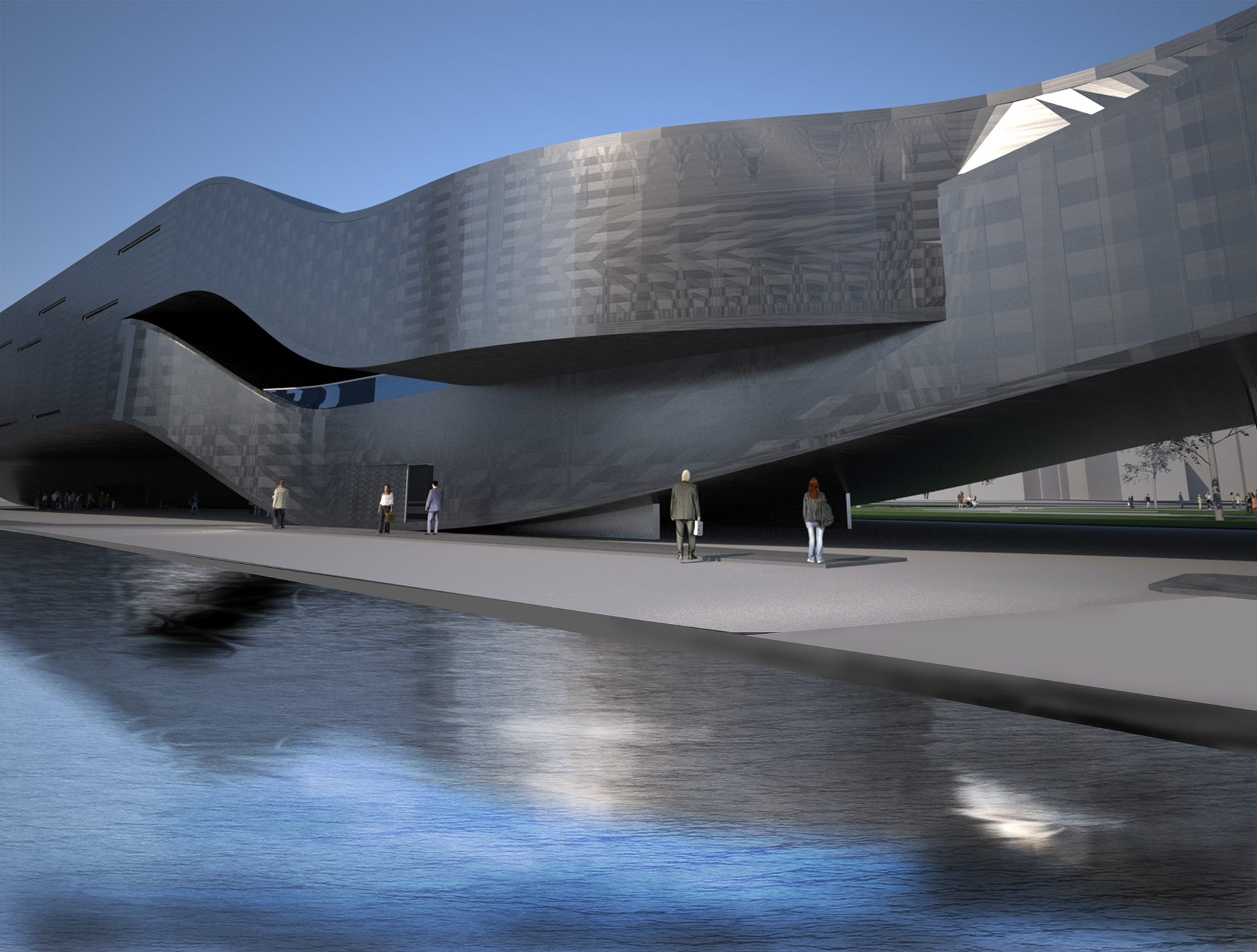
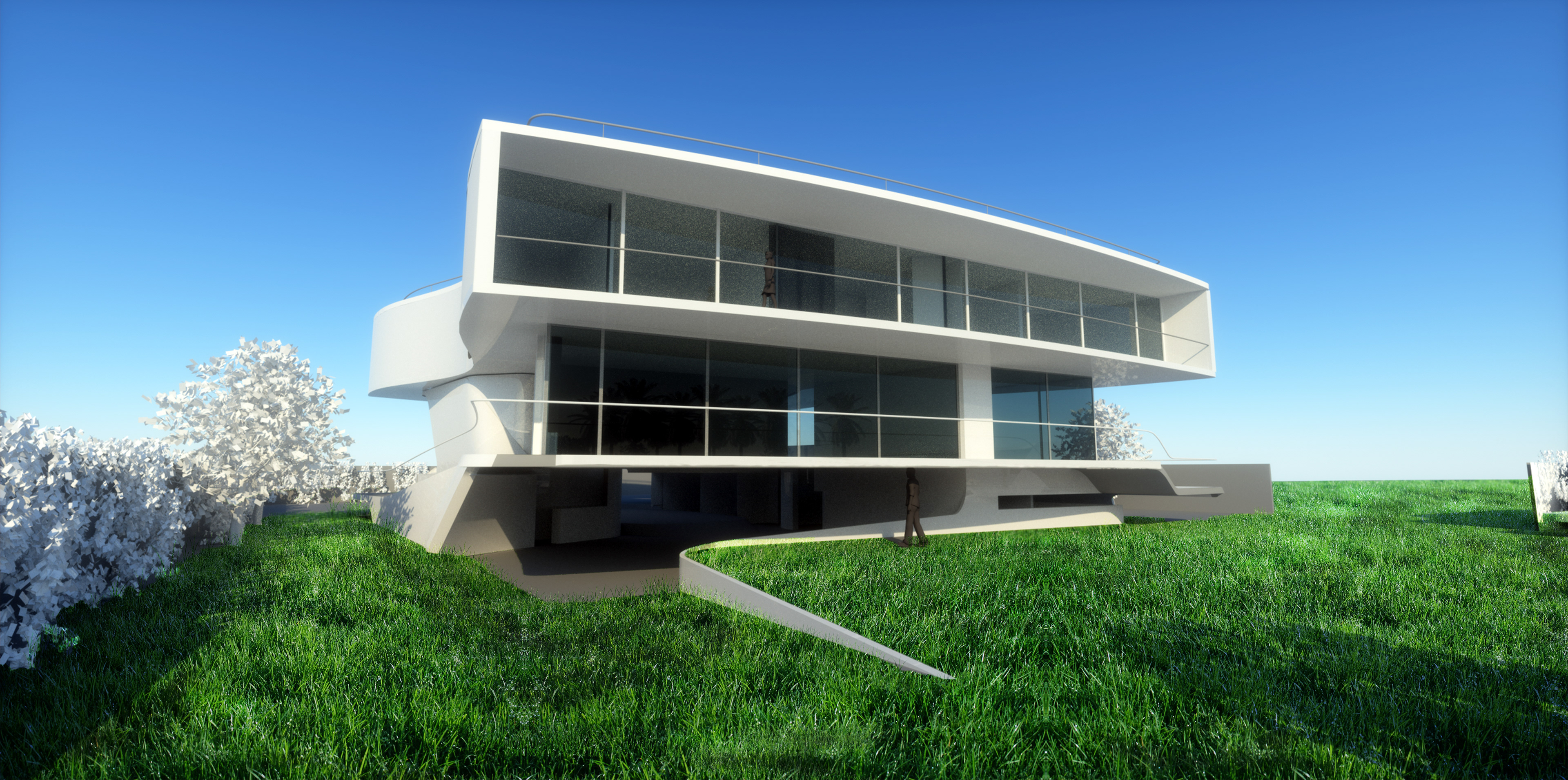
Water mirror and blurring effect done in Photoshop
Grass texture added to site done in Photoshop
After learning several brick stacking bonds, we had a lab to put our knowledge into hands-on practice
Self-designed concrete pour mold results
Rendering of Rhino3D model materials and sky done in V-Ray
Practice Lumion rendering

The first Lumion video I've completed for my Design 5 Charleston project

Environmental Technology lab study on thermal heating distribution for a site
Environmental Technology lab studying lighting systems and comparing incandescent and LED light source energy usage.
Modified Queen truss group lab for my structures course, which was able to withstand the weight of three jars of coins and one and a half concrete blocks.
Materials and Methods case study lab of the Nelson-Atkins Museum Addition studying the structure, wall composition, program, materials, and lighting of the project.
Structures case study lab of the 100 Mount Street Building located in Sydney, Australia. The tower’s highly efficient structural system and exposed mega-bracing are designed to manage the building’s torsional response, while minimizing the size, cost, and carbon footprint of the bracing system. This design helped to reduce steel quantities by 10 percent for lateral loads, while also lessening the impact of vertical creep and shrinkage stresses. 
Both the main lateral structural elements and the floor spanning systems are constructed from concrete which has been cast in place and utilizes steel reinforcement bars and/or steel reinforced concrete. These guiding principles resulted in the exposed structural concrete core, exposed concrete, and steel mega-bracing system, and soaring closed cavity curtain wall system of the building design appropriate for the mild climate of Sydney. - The typical floors are framed with bonded post-tensioned concrete band beams and floor decks The typical framing is supported by just 10 vertical high-strength 14,000 psi concrete columns. The offset concrete core to the West both supports the floors and provides resistance to lateral loading. An efficient core structure required a supplementary lateral system on the East face of the building to balance the inherent torsion and potential movements from eccentric wind loads. The supplementary lateral system also minimized the potential for wind uplift and deep tie-down foundations below the core. The supplementary lateral load resisting system required high lateral stiffness to balance eccentric wind loading and possible uplift on the core. 
Structural steel was chosen as the bracing material to minimize brace sizes and simplify erection and other construction issues. Steel mega-bracing of the concrete columns forms a composite bracing system, adding design complexity from concrete creep and shrinkage and thermal effects. The mega-bracing was initially proposed to be a chevron pattern or “k-bracing” to mitigate the effects of the composite system. The initial bracing configuration is less stiff than an “x-bracing” and also has longer unbraced diagonals which would increase steel tonnages. The most efficient bracing pattern is an x-brace with the central node located at 3⁄4 of the bracing module height. The bracing at 100 Mount Street is located at the 2⁄3rd module point to align with a floor level and is approximately 10% stiffer than an x-brace. This system was selected to maximize the supplementary support offered to the core. 100 Mount Street is the tallest building of its surrounding buildings in Sydney. Because of this, there is not a lot of wind buffer from surrounding buildings. The k-bracing system was developed in order to help combat the wind forces. The structure, without being entirely rigid, also allows for the building to sway with the wind. This allows for more stability and a taller building.
Back to Top